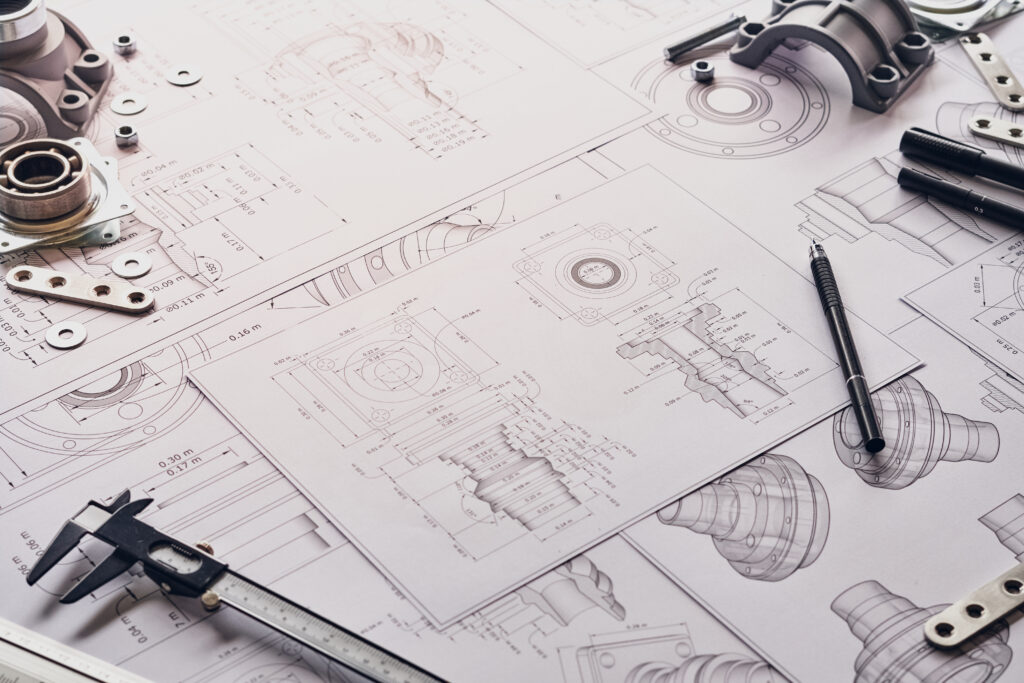
Machining drawings are the foundation of CNC machining processes. They provide the precise blueprints needed to create parts with exact dimensions, intricate features, and specified tolerances.
Whether you’re new to CNC machining or an industry professional, understanding machining drawings is key to achieving accurate and efficient results.
In this guide, we’ll cover everything from the basics of machining drawings to common mistakes and best practices, ensuring you’re well-equipped to read and create detailed technical illustrations for CNC machining.
-
Table Of Contents
-
1. What You Need to Know About Machining Drawings for CNC Machining
-
2. What is a CNC Machining Drawing?
-
3. Key Components of CNC Machining Drawings
-
4. How to Understand CNC Machining Drawings
-
5. Types of Machining Drawings
-
6. Best Practices for Creating Machining Drawings
-
7. Common Mistakes to Avoid
-
8. The Role of CAD Software in CNC Machining
-
9. Understanding Machining Drawing Symbols
-
10. How to Design for CNC Machining
-
11. Summary
What is a CNC Machining Drawing?
A CNC machining drawing is a technical document that outlines the structure, dimensions, and features of a part for CNC manufacturing.
These drawings typically include several key elements, such as a title block, isometric and orthographic views, section views, detail views, and important notes for manufacturers.
At its core, a CNC machining drawing eliminates ambiguity, ensuring that manufacturers and engineers are on the same page before production begins.
These drawings help visualize the part and guarantee that every detail is understood and accounted for.
Key Components of CNC Machining Drawings
1. Title Block: Contains essential information, such as the part name, material, scale, and company details.
2. Isometric View: A 3D perspective of the part that provides a full visual of its design.
3. Orthographic Views: Multiple 2D views (top, front, and side) that cover all angles and dimensions.
4. Section Views: Internal features that may not be visible in standard views are highlighted here.
5. Notes: Include details such as tolerances, surface finishes, or specific manufacturing instructions.
How to Understand CNC Machining Drawings
For beginners, CNC machining drawings can seem overwhelming, but breaking down the document step by step makes it manageable.
1. Start with the Title Block: Review the part’s material, scale, and other key information.
2. Examine the Orthographic Views: These multiple angles are essential for understanding the part’s different sides.
3. Check Section Views: Ensure the drawings accurately capture internal features.
4. Pay Attention to Notes: Important details, such as tolerances or machining requirements, are often included here.
Types of Machining Drawings
Various types of drawings serve different purposes in CNC machining. Understanding each type helps ensure that no critical detail is missed during production.
1. Isometric Drawing: A 3D view of the part that shows its overall shape and design, ideal for complex parts with irregular geometries.
2. Orthographic Drawing: Multi-view drawings (top, front, and side views) provide precise dimensions and are the primary reference for machining.
3. Sectional Drawing: These drawings cut through the part to reveal internal features that need machining, such as cavities or holes.
4. Detail Drawing: Close-ups of intricate sections of a part require focused attention for accurate machining.
Best Practices for Creating Machining Drawings
Producing effective CNC machining drawings requires following specific best practices that ensure accuracy and clear communication between designers and machinists.
1. Keep it Simple: Avoid unnecessary complexity. Focus on essential details that are critical for the machining process.
2. Clear Dimensioning: Ensure all dimensions are labelled clearly, and tolerances are easily understood.
3. Include Only Necessary Views: Too many views can confuse, while too few can leave out essential details. Striking the right balance is critical.
4. Use Appropriate Symbols: To avoid miscommunication, use standardized symbols for tolerances, surface finishes, and other machining instructions.
Common Mistakes to Avoid
Even experienced professionals can make errors when creating or interpreting CNC machining drawings. Here are some common mistakes and how to avoid them:
1. Incorrect Tolerances: Ensure that all tolerances align with the capabilities of your CNC machine. Missing or incorrect tolerances can lead to production errors.
2. Misaligned Views: Verify that all views are correctly aligned to prevent discrepancies in dimensions across the drawing.
3. Overcomplicated Drawings: Too much information can overwhelm machinists, making it harder to focus on critical details. Stick to the essentials.
4. Inconsistent Units: Always use consistent units (inches, millimetres) throughout the drawing to prevent confusion.
The Role of CAD Software in CNC Machining
Computer-Aided Design (CAD) software plays a critical role in creating precise machining drawings for CNC machining.
CAD software enables engineers to create accurate, detailed designs that can be directly translated into CNC machine instructions.
Popular CAD programs for CNC machining include:
• AutoCAD: Widely used for both 2D and 3D machining drawings, known for its versatility.
• SolidWorks: Popular among engineers for its ability to handle complex 3D models and part drawings.
• Fusion 360: A cloud-based solution with integrated CAM (Computer-Aided Manufacturing) features.
• CATIA: Known for its use in aerospace, this software offers advanced design and simulation tools.
These CAD tools make it easier for engineers to design parts that are optimized for CNC machining and to generate accurate drawings that reduce the risk of production errors.
Understanding Machining Drawing Symbols
Symbols are used extensively in CNC machining drawings to convey essential information without cluttering the document with excessive text.
These symbols communicate specific details about the part’s tolerances, surface finishes, and machining processes.
Commonly used symbols include:
• Geometric Dimensioning and Tolerancing (GD&T): Indicates a part’s geometry tolerances.
• Surface Finish Symbols: Show the surface finish required, whether smooth, rough, or specific textured finishes.
• Hole Specifications: Symbols like counterbore or countersink detail the specific requirements for drilled holes.
How to Design for CNC Machining
When designing parts for CNC machining, there are several important design considerations to keep in mind to ensure manufacturability and cost efficiency:
1. Maximize Tool Diameter: Designing parts that can be machined using the largest possible tool diameter reduces machining time and wear on tools.
2. Add Large Fillets: Incorporating larger fillets in internal corners helps prevent stress concentrations and reduces the risk of tool breakage.
3. Limit Cavity Depths: Deep cavities are more challenging to machine. Limiting cavity depths to a reasonable proportion (four times their width) helps prevent issues during production.
Conclusion
Understanding CNC machining drawings is essential for anyone involved in the CNC machining process, from design engineers to machinists.
These drawings serve as the foundation for producing accurate, high-quality parts, ensuring that all dimensions, tolerances, and features are clearly communicated before production begins.
By following best practices, utilizing CAD software, and avoiding common mistakes, you can streamline the machining process and achieve better results.
Whether you’re designing complex components or interpreting detailed drawings, a solid grasp of CNC machining drawings will significantly improve the quality and efficiency of your work.